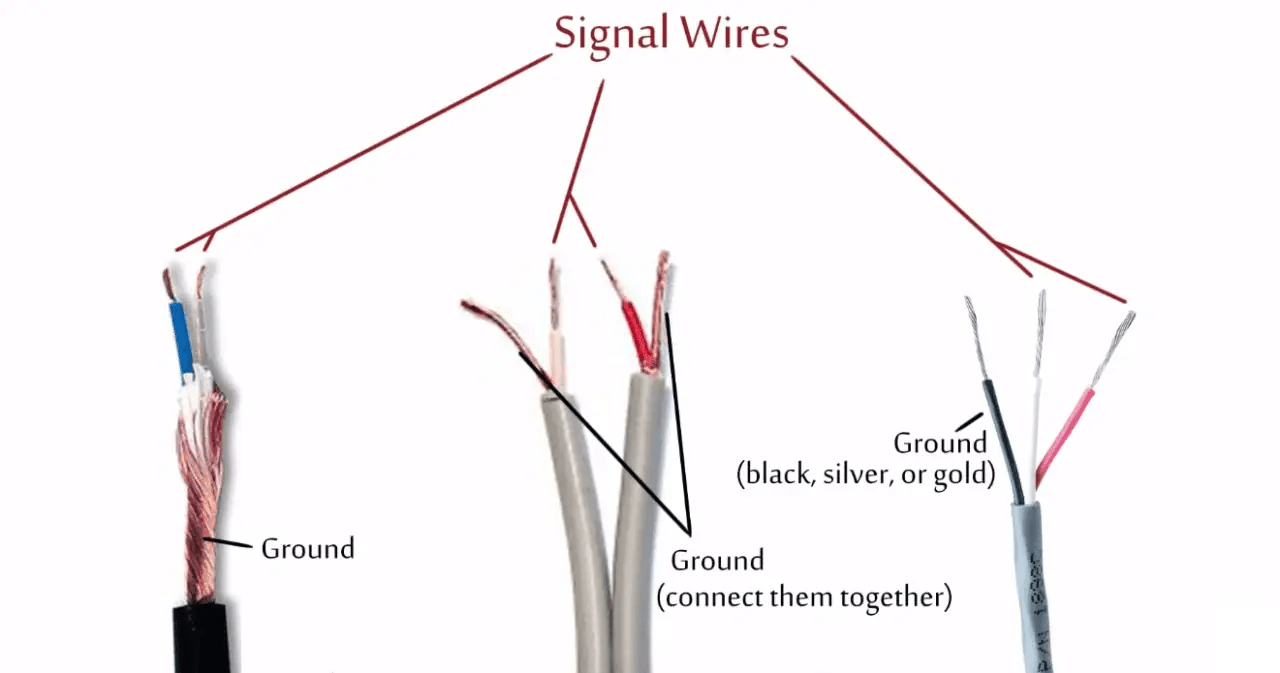
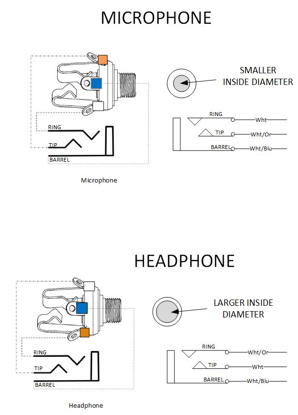
Unlocking the Secrets of Headphone Plug Wiring: Your Ultimate Guide
Ever wondered what magic happens inside that tiny headphone plug? It's not magic, it's a carefully orchestrated arrangement of wires, each with a specific purpose in delivering crisp, clear audio. Understanding the headphone plug wiring diagram empowers you to troubleshoot connection issues, repair broken headphones, and even customize your audio experience.
A headphone plug, also known as an audio jack or phone connector, is the interface between your headphones and your audio source. These plugs come in various configurations, the most common being TRS (Tip-Ring-Sleeve) for stereo sound and TRRS (Tip-Ring-Ring-Sleeve) for stereo sound plus a microphone. Navigating the world of headphone plug wiring can seem daunting, but with a little knowledge, you can demystify these connections.
The earliest headphone plugs were simple mono connections. As technology advanced, the demand for stereo sound led to the development of the TRS connector. Later, the rise of mobile devices with integrated microphones necessitated the addition of another ring, resulting in the TRRS plug. Understanding this evolution helps contextualize the different wiring standards we encounter today.
The correct headphone jack pinout is crucial for proper functionality. An incorrect connection can result in no sound, reversed stereo channels, a non-functional microphone, or even damage to your device. That's why understanding the headphone wiring schematic – the blueprint of the plug's internal connections – is so important.
There are two dominant standards for TRRS wiring: CTIA (Cellular Telephone Industries Association) and OMTP (Open Mobile Terminal Platform). While both carry audio and microphone signals, the ground and microphone connections are swapped. This seemingly minor difference can cause compatibility issues between headphones and devices. Knowing which standard your devices use is vital for a seamless audio experience.
A standard TRS headphone plug wiring diagram reveals three contacts: Tip (left audio), Ring (right audio), and Sleeve (ground). A TRRS diagram adds a second ring for the microphone. Understanding these connections is the first step in troubleshooting and repair.
One benefit of understanding the headphone plug wiring diagram is the ability to repair broken headphone cables. Instead of discarding your favorite headphones, you can replace the cable or re-solder broken connections, saving money and reducing electronic waste.
Another advantage is the ability to create custom audio setups. You can adapt headphone cables to work with different devices or even build your own headphone amplifiers with a clear understanding of the underlying connections.
Finally, knowledge of these diagrams helps troubleshoot audio issues. If one earbud stops working, you can pinpoint the problem within the cable or plug, eliminating guesswork and streamlining the repair process.
If you're facing audio issues, a multimeter can be used to test the continuity of the connections within the plug and cable, helping you isolate the problem area. Online resources offer detailed headphone plug wiring schematics for various connector types and standards.
Advantages and Disadvantages of Understanding Headphone Wiring
| Advantages | Disadvantages |
|---|---|
| Repair broken headphones | Requires some technical knowledge |
| Create custom audio setups | Risk of damaging equipment if done incorrectly |
| Troubleshoot audio issues |
Best practices include using high-quality solder and wire for repairs, ensuring proper insulation to prevent shorts, and verifying connections with a multimeter after soldering.
Common challenges include identifying the correct wiring standard, dealing with very thin wires, and ensuring proper grounding. Solutions involve consulting detailed diagrams, using magnifying glasses and precision tools, and meticulously checking connections.
FAQs include questions about the difference between TRS and TRRS, CTIA vs. OMTP, how to identify broken connections, and where to find replacement parts.
Tips and tricks include using heat shrink tubing to protect solder joints, using color-coded wires for easier identification, and testing connections with a known working audio source.
In conclusion, the headphone plug wiring diagram, whether for a TRS, TRRS, or other configuration, is a fundamental piece of knowledge for anyone who uses headphones. Understanding the intricacies of these connections empowers you to troubleshoot, repair, and customize your audio setup. From fixing a broken cable to building a custom amplifier, this knowledge unlocks a world of possibilities. Take the time to learn about headphone jack wiring – your ears will thank you. By understanding the core principles and seeking out reliable resources, you can confidently navigate the world of headphone plug wiring and ensure a consistently high-quality audio experience.
Elevating exterior wood a look at behr paint
Unlocking potential top young right wingers in fifa 23
Understanding your water pumps pressure control

35 Mm Audio Wiring Diagram | Solidarios Con Garzon

Headphone Jack Plug Wiring Diagram | Solidarios Con Garzon

Stereo Audio Jack Pinout | Solidarios Con Garzon

How To Wire 35 Mm Audio Jack | Solidarios Con Garzon

Headphone Wiring Diagram Colors | Solidarios Con Garzon

Android Headphone Plug Wiring | Solidarios Con Garzon

Headphone Wiring Color Code | Solidarios Con Garzon

Headphone Jack Wiring Colors | Solidarios Con Garzon

Headphone Microphonebo Wiring Diagrams | Solidarios Con Garzon

Wiring A Headphone Jack | Solidarios Con Garzon

Headphones Wiring Color Code | Solidarios Con Garzon

Stereo Headphone Jack Wiring | Solidarios Con Garzon

Headphone Jack Wiring Diagram Xperia | Solidarios Con Garzon

Headphone Plug Wiring Diagram | Solidarios Con Garzon

Wiring Diagram For Headset Jack | Solidarios Con Garzon