Unlocking Hydraulic Systems: Your Guide to Hydraulic Symbol Charts
Imagine trying to assemble a complex piece of machinery without a clear set of instructions. Frustrating, right? The same applies to hydraulic systems. Navigating the intricate network of pumps, valves, and actuators requires a universal language – and that's where hydraulic schematics and their corresponding symbol charts come in. These visual guides, often available as downloadable hydraulic symbols chart PDFs, provide a standardized way to represent and interpret hydraulic circuits, ensuring clarity and efficiency in design, maintenance, and troubleshooting.
Hydraulic systems are the backbone of countless industries, powering everything from construction equipment and agricultural machinery to aircraft and industrial robots. These systems rely on the power of pressurized fluids to generate, control, and transmit force. A hydraulic symbol diagram, based on a standardized hydraulic symbols chart, acts as a roadmap for these intricate systems, enabling engineers, technicians, and operators to understand how each component interacts and contributes to the overall functionality.
The development of standardized hydraulic symbols was a gradual process, driven by the need for clear communication and interoperability within the industry. Early hydraulic diagrams were often inconsistent and difficult to interpret. As hydraulic technology advanced, so too did the need for a universally recognized system of symbols. Organizations like ISO (International Organization for Standardization) played a critical role in establishing and refining these standards, culminating in comprehensive hydraulic symbols chart PDFs readily available today.
One of the main issues addressed by standardized hydraulic symbol charts is the ambiguity that can arise from inconsistent representation. A universal visual language minimizes the risk of misinterpretation, ensuring that everyone involved in the design, operation, and maintenance of hydraulic systems is on the same page. This standardization is particularly critical in complex systems where a single misinterpretation can lead to costly errors, downtime, or even safety hazards.
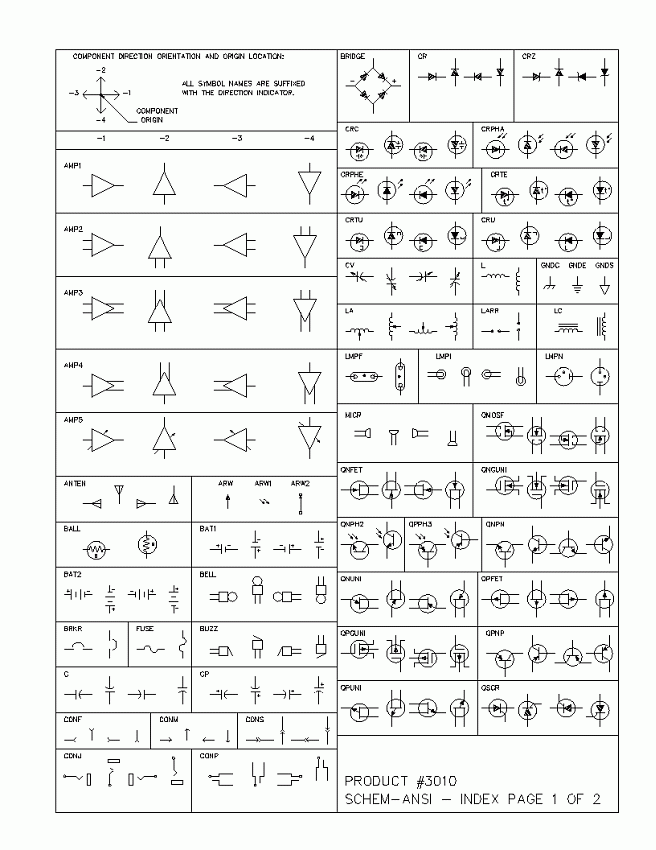
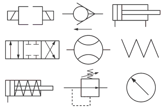
A hydraulic symbols chart, often distributed as a convenient hydraulic symbols chart PDF, serves as a dictionary for decoding hydraulic diagrams. Each symbol represents a specific hydraulic component, such as a pump, valve, actuator, or filter. These symbols are designed to be easily recognizable and unambiguous, providing a clear visual representation of the component's function within the system. For instance, a circle with an arrow indicates a directional control valve, while a rectangle with a piston represents a hydraulic cylinder.
One key benefit of using a standardized hydraulic symbols chart PDF is improved communication. These charts facilitate a common language for engineers, technicians, and operators worldwide, streamlining collaboration and troubleshooting.
Another advantage is enhanced safety. By providing a clear understanding of the hydraulic system's layout and operation, these charts reduce the risk of errors and accidents during maintenance and operation.
Finally, standardized symbols promote efficiency. They simplify the design and analysis of hydraulic systems, enabling engineers to quickly identify potential problems and optimize performance.
When using a hydraulic symbols chart, ensure you have the latest version reflecting current industry standards. Familiarize yourself with the symbols and their corresponding components. Use the chart consistently across all documentation and communication related to the hydraulic system.
Advantages and Disadvantages of Using a Hydraulic Symbols Chart PDF
| Advantages | Disadvantages |
|---|---|
| Easy access and portability | Requires updating to maintain current standards |
| Clear and standardized representation | Can be overwhelming for beginners without proper training |
| Facilitates communication and collaboration | Potential for misinterpretation if used incorrectly |
Best Practice 1: Use the latest version of the ISO standard for hydraulic symbols.
Best Practice 2: Ensure all team members are trained on how to interpret the symbols.
Best Practice 3: Consistently apply the symbols throughout all project documentation.
Best Practice 4: Refer to the hydraulic symbols chart PDF when troubleshooting system issues.
Best Practice 5: Incorporate the chart into training materials for new personnel.
Frequently Asked Questions:
1. Where can I find a reliable hydraulic symbols chart PDF? Answer: Several industry organizations and websites offer downloadable PDFs.
2. Are there different standards for hydraulic symbols? Answer: Yes, though ISO standards are widely adopted.
3. How often are hydraulic symbols updated? Answer: Standards are periodically reviewed and updated to reflect technological advancements.
4. Do I need special software to view a hydraulic symbols chart PDF? Answer: No, a standard PDF reader is sufficient.
5. What are the basic symbols I need to know? Answer: Basic symbols represent pumps, valves, actuators, and lines.
6. How can I learn more about hydraulic system design? Answer: Several books and online courses cover hydraulic system design principles.
7. Are there any mobile apps for accessing hydraulic symbols? Answer: Yes, some apps provide access to hydraulic symbol libraries.
8. What's the difference between a hydraulic schematic and a hydraulic symbols chart? Answer: The chart defines the symbols, while the schematic uses those symbols to represent a specific system.
Tips and tricks: Print out a laminated copy of the hydraulic symbols chart PDF for quick reference in the field. Use digital versions on tablets for easy access during maintenance. Consider creating custom symbol libraries for specific applications.
In conclusion, understanding and utilizing hydraulic symbol charts, particularly in a readily accessible format like a hydraulic symbols chart PDF, is essential for anyone working with hydraulic systems. These charts provide a standardized language that fosters clear communication, enhances safety, and improves efficiency across all stages of system design, operation, and maintenance. By embracing best practices and staying up-to-date with the latest standards, you can unlock the full potential of hydraulic technology while minimizing the risks associated with misinterpretation and errors. Investing time in understanding these symbols is an investment in the safety, efficiency, and success of your hydraulic projects. So, take the time to familiarize yourself with a hydraulic symbols chart today. It's a small step that can make a big difference. Don’t let ambiguity hold your hydraulic projects back – empower your team with the knowledge they need to succeed.
Craving comfort food the red lion diner menu awaits
Avoid cashiers check scams targeting wells fargo customers
Sunset funeral home grand falls windsor what nobody tells you

Hydraulic Symbols Pdf Download | Solidarios Con Garzon

Pneumatic Circuit Valve Symbols at Luis Abbott blog | Solidarios Con Garzon

Hydraulic System Drawing Symbols | Solidarios Con Garzon

Hydraulic Schematic Symbols Chart Pdf | Solidarios Con Garzon

Hydraulic Circuit Symbols Explanation | Solidarios Con Garzon

Hydraulic And Pneumatic Components Pdf at Sherry Barrera blog | Solidarios Con Garzon

Hydraulic Schematic Symbols Library Free | Solidarios Con Garzon

Hydraulic Schematic Symbols Pdf | Solidarios Con Garzon

Hydraulic Schematic Diagram Symbols | Solidarios Con Garzon

Graphical Symbols For Hydraulic Circuits | Solidarios Con Garzon

Symbols Of Hydraulic System | Solidarios Con Garzon

hydraulic symbols chart pdf | Solidarios Con Garzon

hydraulic symbols chart pdf | Solidarios Con Garzon

Standard Hydraulic Schematic Symbols | Solidarios Con Garzon

Symbols For Hydraulic Schematics | Solidarios Con Garzon